An unmanned hovercraft with plywood hull, a skirt made from a painter's dropcloth, and a leaf-blower engine; plus build your own 10-minute pizza-box hovercraft!
Hovercraft
with Jay Wilson
May 1999
Contents
I “suffered greatly” in my youth from a lack of access to small internal combustion engines for powering various experimental vehicles. My fortunes changed dramatically when Jay Wilson and I suddenly came across an embarassement of riches: not one, but two single cylinder lawn-care tools. Here was the perfect opportunity to terrorize my neighborhood with some sort of roaring, smoking, dangerous contraption!
Always ready to fritter away good fortune, Jay and I decided that what we really needed was a project that used both engines at once. After discussing a tank-treaded vehicle and various wheeled instruments of mayhem, we began planning a hovercraft - an especially suitable idea since one of the lawn tools was a leaf blower. Perfect for the lift engine! Of course, since our engines were no match for the weight of even one mad engineer, radio control was selected to keep the beast on a leash.
Simple Models
First, however, we needed to conduct some experiments, to increase our understanding of, and confidence in, the principles of hovercraft flight. Some Internet research yielded plans from Bill Nye the Science Guy for a simple hovercraft using plastic garbage bags as a skirt.

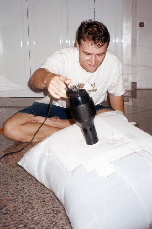
This hovercraft consists of a flat plate of cardboard, with a bag attached underneath and fixed in the middle with a piece of tape, in order to form a concave space to contain the air cushion. Unfortunately, the design is far too reliant on this one piece of tape (just how strong can a doubled over tape joint be?). It tends to fail, allowing the 'hovercraft' to become rather like a balloon, as can be seen in the photos above. Jay's expression in the second one says it all!
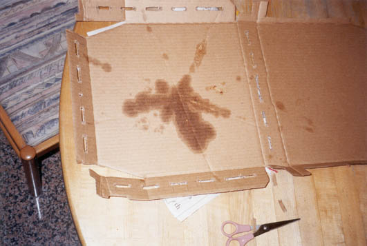
That same night, after the midnight engineer's customary dinner of delivery pizza, inspiration struck: we would use the pizza box as the hull and air-delivery manifold of the model! Several slots were cut into the sides of the box to allow air in the skirt, and a precise circular hole in the middle of the top provided a decent friction-fit with the hair dryer. The box was sealed with clear packing tape after some of the folds of the pizza box were removed to simplify the shape and reduce unnecessary weight.
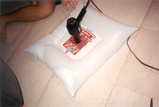
A particularly clever aspect of this design is the attachment of the garbage bag skirt. This medium size of bag can be laid flat as a rectangle. We simply put the pizza box inside this, and cut a square out of the top 'sheet' of the bag, revealing the top of the box. We taped the bag to the cardboard around the periphery of this hole, then repeated the process on the bottom side. Finally, we sealed the end of the bag with more packing tape. In this case, a series of holes cut into the inside bottom of the bag itself provided air to the cushion; it would also be possible to cut such holes in the pizza box instead. The picture above reveals the completed machine hovering on the floor. We were fortunate in using a hair dryer with a circular output; other shapes might require tape for sealing or support.
The Full-Size Machine
With confidence propped up by cardboard success, it was time to scale up our design. The final craft was to consist of an angular wooden hull, a skirt made of a painter's dropcloth, and the aforementioned lawn blower engine and fan. The hull is trapezoidal in cross-section, in order to push the skirt tubes further below and so trap a larger air-cushion. Additionally, the front and back of this hull is angled inwards for a sleeker appearance.
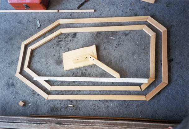
We achieved this shape by building two frames of douglas fir, one each for the top and bottom of the hull. Making the lower frame smaller than the top yields a kind of 3-d 'trapezoid', with the sides sloping inward from top to bottom by 45 degrees all around the perimeter. The photo above shows these concentric frames before they were attached together (the white bar is a yardstick, for scale); fabrication involved ripping the stock to 45 degrees, then carefully mitering pieces together with glue and one nail each. As separate frames, they were quite weak (too much force could cause the joints to swivel), but this method of construction became suprisingly strong when completed. Indeed, it probably should have been weakened somewhat to make it lighter.
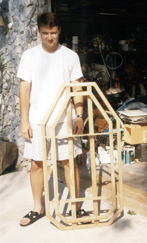
This picture shows the complete assembly. There are two important details to observe. First, the two frames are held together with quarter-inch thick plywood bulkheads. These we cut to a trapezoidal shape and inserted into quarter-inch slots in the frame members ('dado' joints, to a woodworker) We drilled numerous large holes in the bulkheads to reduce weight and allow lift air to enter the ends of the craft - these holes are hard to see directly in the photo, but are visible in the shadow cast by the frame.
Second, the top (larger) frame includes two lengthwise fir beams intended to strengthen the 'deck' of the hovercraft. These are especially important as they provide mounting points for the two engines and any other hardware that needs to ride on top. The beams are attached to the frame at each end with a single large dovetail, cut entirely by hand. In fact, aside from the small nail in each mitre joint, there is not a single metal fastener in the entire structure. Neccessary? Efficient? NO - but worthy of respect!

We covered the skeleton in 1/16 inch thick plywood - specifically, the cheap mahogany veneer known as 'lauan doorskin' (named as such because doors are made from it). The photo above shows an almost completed hull, with the bottom still to be attached. A perimeter of large holes allows air to exit the bottom plate and enter the air cushion underneath the vehicle. Smaller holes in the sides of the hull keep the skirt inflated in order to trap the cushion. It is possible to simply build a rigid tray for this purpose underneath the hull, and indeed, Sir Cockerell's first few hovercraft used just that. However, the pioneers of air-cushion vehicles soon discovered that a flexible skirt is better able to conform to uneven ground or waves at sea, thus providing a better seal for the air cushion.
Observe also the white circle in the middle of the top sheet. This is the air inlet - a pvc fitting tightly fitted into the skin and caulked. Some other pipe fittings and hose clamps allowed us to connect the lawn blower to this without losing much air at all.
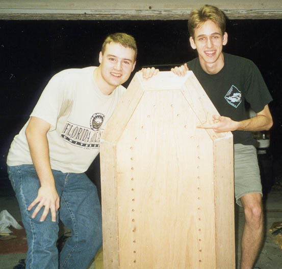
Proud inventors pose with the fruit of their labors!
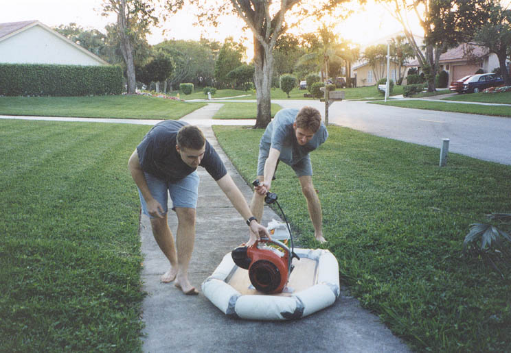
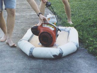
The skirt in the photo above is painter's dropcloth, a thin sheet of fabric coated with butyl rubber and hence reasonably airtight. As you can see, it has been tailored with duct tape. One of the most annoying topological problems in fitting fabric together is "mitring" the round sections such that they inflate in the right shape. Theory tells us that the flat fabric should be cut along a kind of s-curve to make the angled joint correct when it is rolled up and inflated. Ours is hardly perfect, as can be seen in the photo, but it worked well enough.
The lift engine was not firmly attached at the time of this photo, which is why Jay reaches out to steady it. We placed a large bottle on the back to balance the craft and prevent too much air leaking out the back of the cushion. I am operating the throttle control of the lift engine.
This is, unfortunately, the only known picture of the craft hovering. Jay and I dropped this project shortly afterward to work on speakers instead, although we might pick it up again, as we still have the propulsion engine and have since gained more experience in subjects like servo control.