My senior university project, an articulated pipe inspection robot with a new kind of screw-drive propulsion and an inertial navigation system.
The Pipe Crawler
with Sheraz Wasi
and Mark Miller
May 2003
Contents
- Dramatis Personae
- Goals
- The Screw Drive
- Some Models
- Electronics and Sensors
- Hollow Shaft Gear Drive
- 0.3 Thousandths of an Inch for 20 Dollars
- Dodgy Electrics
- Final Assembly
- Rage Against the Machine
- If I HAD to Do it Again
For More on this Project
Pipe inspection is one of those specialized killer apps of robotics, like exploring space or mowing the lawn, that have spawned a remarkable number of experimental attempts, working machines for industry, and even (in the case of mowing the lawn) consumer products. Examples of pipe-crawling robots pop up every couple of months in the popular scientific magazines (Popular Science especially). Despite my earlier vow not to build a robot as my engineering design project, in October of 2002 my team had just given up the idea of building another old favorite of applied robotics, the automated golf caddy. Forced by the class deadline to come up with another idea in about 10 minutes, I brought my knowledge of those science magazines to bear; the cool-looking pipe inspection robots I had read about crawled slowly into my vision! The rest of my team accepted this idea, and we presented it to the faculty. Although they questioned and criticized for form's sake, they approved it eagerly, condemning our team to lunatic months of 16 hour days, take-out Chinese, and constant mad scramble on a never-before-seen scale—the worst semester of our lives!
But that dark future was far from our minds in those innocent days of October; we were happy that our proposal was accepted and set to work, researching other pipe inspection robots, outlining the scope of our project, and solving conceptual problems. But first, an introduction to the team itself.
Dramatis Personae
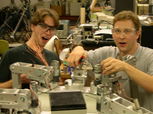
Beyond myself, the pipe crawler team consisted of two of FAU's finest gentlemen, electrical engineers, and mischief-makers, Sheraz Wasi and Mark Miller.


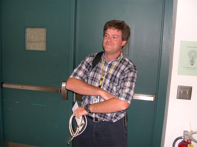
Mr. Wasi can be seen on the left above, reacting in pain as the FAU walking robot siezes him by the wrist in retaliation (more on this later). Mr. Miller was responsible for programming the microcontroller; that is probably what induced the keyboard-pounding rage evident in the center photo. Finally, our project advisor was robot expert, talented machinist, system administrator, and general jack-of-all trades Tom Kelly, seen barring the robot lab door to prevent us exiting in favor of the FAU pub.
Goals
To distinguish ourselves from earlier efforts, we decided our robot would meet several ambitious criteria. First, the machine was to be able to travel through horizontal segments, around corners, and straight up. This last requirement rules out a simple rover or wheeled cart. To maintain itself in a vertical section, the robot has to press wheels against the sides of the pipe by mechanical means (ruling out serpentine or inchworm mechanisms—but these also have to press something at least against the walls).
The Screw Drive
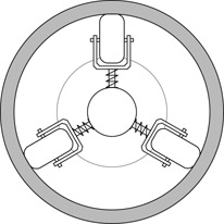
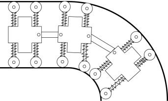
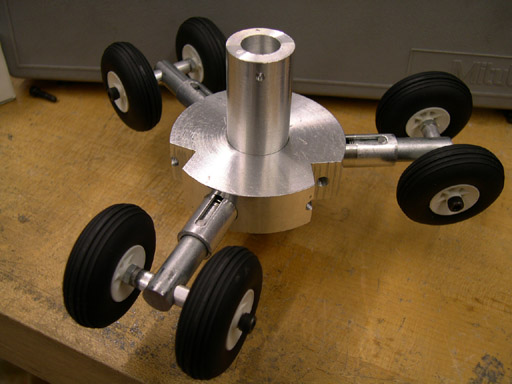
We selected a radial arrangement of three sprung wheels as in the picture. The robot would consist of many such units, articulated like a railroad train, so that it could negotiate corners.
Propulsion could be provided by driving these wheels, but this would require a lot of small motors, or one large motor—driving the wheels through some kind of 120 degree, three output differential (One FAU professor, Dr. Abtahi, suggested that such a device could make use of fluid power, but that developing and building one would consitute an ambitious senior project itself). So we started thinking along a different line: could we use the pipe as a track to keep on course, and simply apply a forward force to make the thing move? The answer is yes—but it may not be any easier!
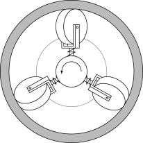
We named the device in the picture above "the screw drive". It consists of an arrangement of free-spinning wheels just like that of the guidance units, but with each wheel angled somewhat (maybe 10 degrees from perpendicular) like the blades of a turbine. Turn the entire assembly and the drive screws forward in the pipe, pulling the robot along. This device requires only one motor per driven section and has the virtue of "gearing-down" this motor, providing the force (albeit at low speed) necessary to climb vertically.
Some Models
We put together several models of this and other mechanisms. The evolution of these is illustrated in the sequence of photos below.
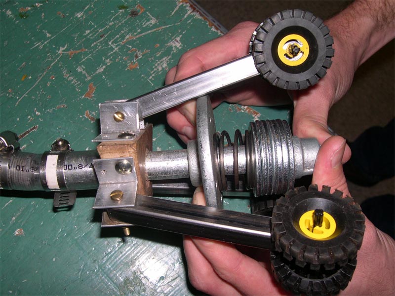
Our first attempt at non-driven guide wheels and articulation: three wheels (yes, LEGO wheels) mounted on arms, pushed out by a large central spring. Two such arrangements are built on pipe segments and attached with a bit of clear vinyl tube and hose clamps.
An alternative to the angularly sprung swing arms is depicted in this picture. Each pair of wheels is attached to a plunger device with a compression spring. The slot and the pin stop the piston rotating.
A first try at the screw drive consisted of a rude wooden cylinder, simple plungers of square section, and a cordless drill driving a long threaded rod. It worked pretty well — watch the video!
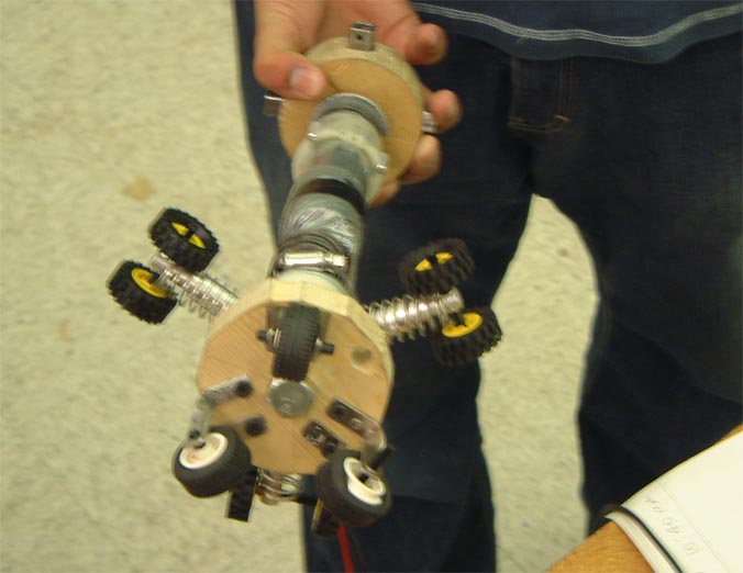
Our first self-contained screw drive used the wood rotor of the drill-powered device. This was driven by the same drill motor, but removed from the drill and made into a more compact shape—of course, very much duct tape can interface virtually anything to anything else! Unfortunately, this model suffers from a lack of torque, as the built in torque limiter of the drill starts clicking away far too soon. Even worse, this feature is integral to the gearbox and cannot be removed without destroying the whole thing. A guide wheel segment is attached to the front, with some small wheels intended to ease the transition through elbows.
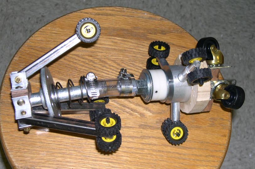

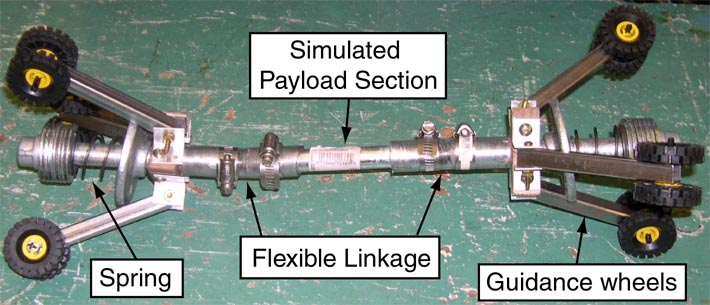
We constructed a combination of angular and linear guide wheels to see if there was some advantage to leading with the straight sprung unit and following with the angular one. Additionally, the small front wheels were replaced with furniture casters—it was discovered that the castering action was unnecessary, but that the hard plastic wheels allowed some slippage, a better result than the soft rubber tires used before.
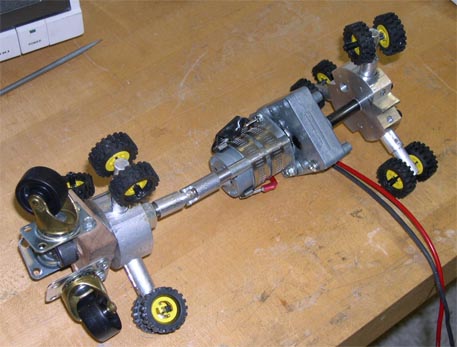
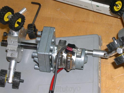
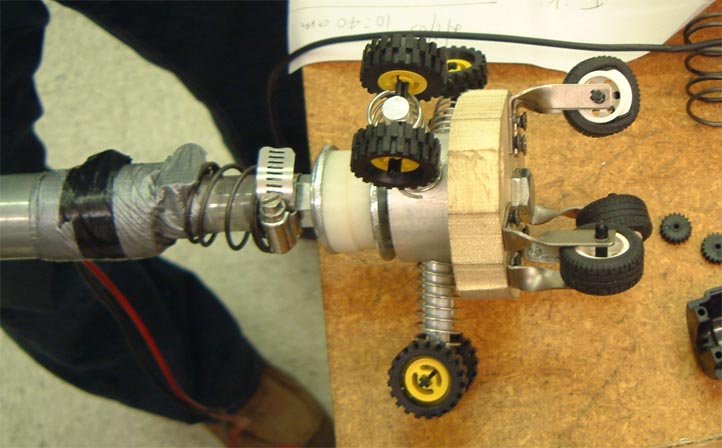
This model features a new, better looking screw drive, driven directly by a gear motor and linked to the head segment of the last model. The articulation consists of a small universal joint. Hose clamps make for a surprisingly rigid connection to the motor.

The Brevel gearmotor used in this last model came from surplus prototypes of anti-theft-tag removal machines made by Sensormatic Electronics. This motor, and another identical one, would power the final pipe crawler as well.
Electronics and Sensors
Once in the pipe and moving around, the machine had to DO something. As a pipe inspection robot, it had to inspect the pipe, right? Since our 'robot' was intended for tele-operation by a human located at the pipe entrance, we needed some means of communication with it (we talked about radio for a while, maybe using the pipe itself as a waveguide, but settled on a simple tether instead), on-board sensors and a video camera for navigation and inspection, and some type of (very small!) computer to sort all the signals out.
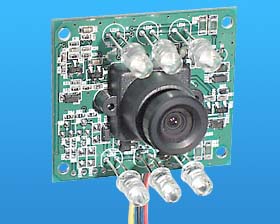
The video camera was easy enough—a simple monochrome board camera, sensitive to IR, with six IR LEDS surrounding the optics, available from Marlin P. Jones for 50 dollars. We tested this in a pitch-black room and found that it can illuminate an object easily up to ten feet away; a small set screw allows adjustments of the focus, although the camera gives a sharp picture on a considerable range of distances without adjustment.
But video cameras are far too common and obvious with robots of this kind—we needed something novel, as we persisted in delusions (encouraged by our advisors) that the project was too easy. We decided on a system of position tracking using inertial navigation. By the fall of 2002, Analog Devices had introduced some micro-electro-mechanical accelerometers and gyroscopes in tiny surface-mount packages. Three orthogonally located gyroscopes could track the rotational axes of yaw, pitch, and roll. As for linear motions, since the robot is confined inside a pipe and unable to shift laterally, motion along only one (forward) axis needs to be recorded, best done by measuring the length of the deployed tether.
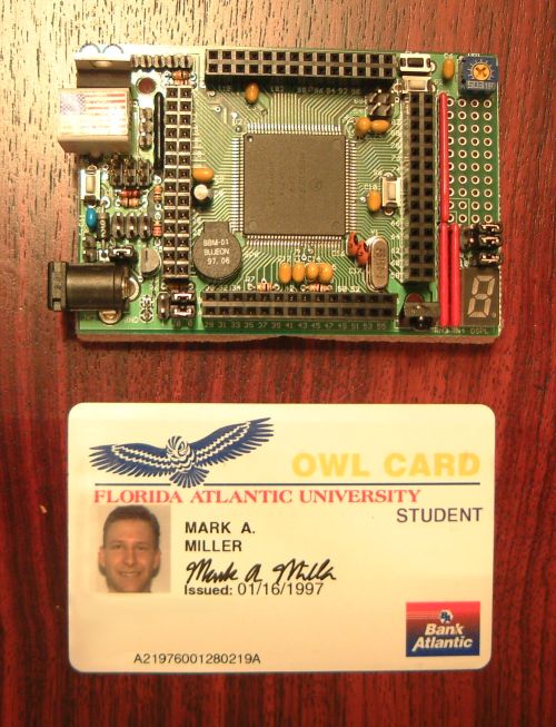
We looked at several small microcontrollers and settled on the Wytec MiniDragon, a small (about the size of a credit card—see the photo above) one-board computer based on the Motorola HC12 processor. The MiniDragon includes several channels of analog to digital conversion and pulse counting, useful for gathering our sensor signals; it can serially communicate via an RJ12 jack (seen in the photo covered with an American flag sticker).
Hollow Shaft Gear Drive
There is an obvious problem with the screw drive idea. With a spinning rotor of wheels going out to the walls of the pipe, where do you pass wires from one end to the other? What structure do you attach the next section to?
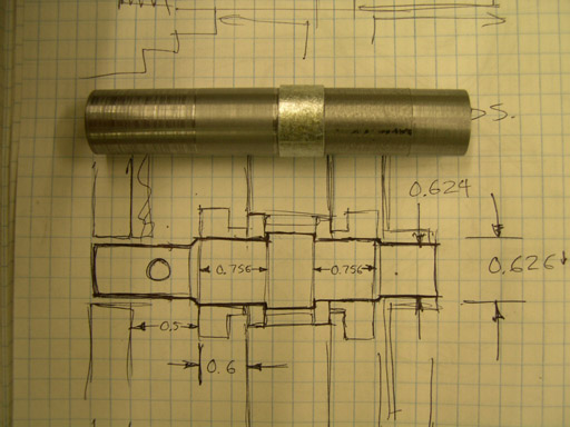
Our solution is an offset drive with a hollow center shaft. A large ring gear is attached to the face of the screw drive hub and turned by a smaller pinion (also gearing the drive down a bit more). The shaft is nothing but a 3/8 inch galvanized steel pipe nipple turned on the lathe and drilled at either end; the slightly larger diameter segment at the center is a stop for the two bearings that the screw drive rides on. Since the hub turns on this shaft, instead of being directly connected to the motor, we could attach the next segment of the robot to the end of the shaft, and pass wires through the hollow center, by means of the holes at the ends.

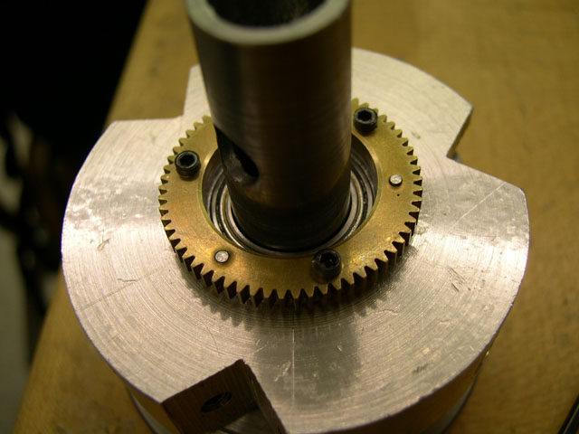
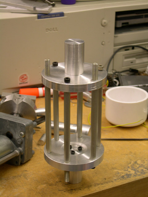
We put together this elaborate contraption as a jig to ensure accuracy when drilling the gear face and hub. The ring gears are attached with three tool pins and three cap screws each.
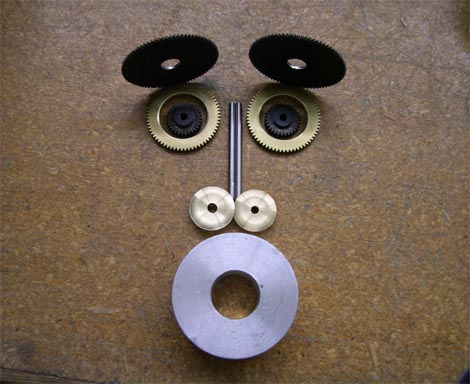
Lastly, we present a monkey, made, in a fit of labor-induced madness, of gears and other mechanical parts.
0.3 Thousandths of an Inch for 20 Dollars
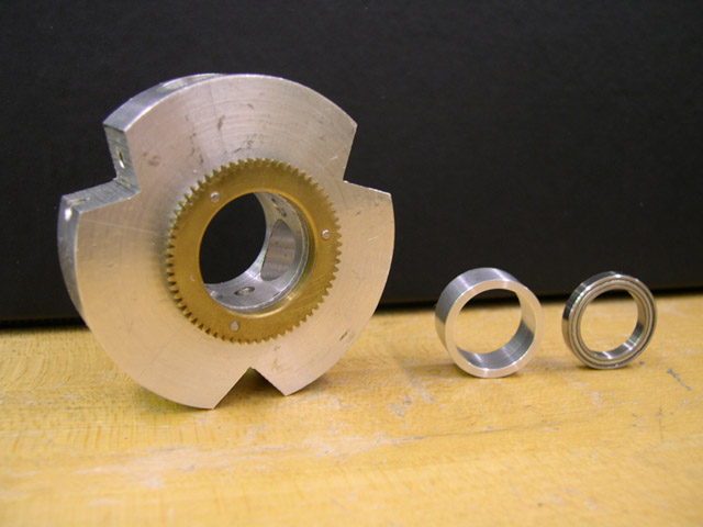
Our screw drives each made use of a pair of rather nice ball bearings. These needed to have a large inner diameter to accept as much of a shaft as possible (for structural reasons, and to give us enough space to run wires), but needed to be as small as possible on the outside so as not to prevent the plunger units from traveling. Therefore, we had to buy these precision, over-engineered, extremely thin ring bearings at $20 each from an outfit called Boca Bearings.
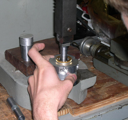

Pressing the screw-hub assemblies together was not easy—the process involved several custom alignment fixtures, chilling the shaft in the shop freezer, and following a rather complex procedure of assembly steps. It worked beautifully … the first time.
The second screw-drive worked less well. After everything was assembled, we found that the hub did not rotate smoothly at all. Apparently, the shaft had not been machined to proper diameter, and was something like 2 thousandths larger than it needed to be—fatal for such tiny bearings.
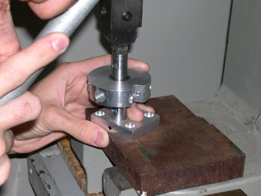
Disassembly was easy, except for the second bearing, which was located in such a way that it was difficult to get any purchase on it with the press. We borrowed a bearing puller, and started applying pressure. Nothing happened, so we applied more pressure. It became clear that we were warping the bearing heavily, and that the only way to get it off was to break it off. More pressure!
When it finally failed, the bearing exploded apart with so much energy that balls hit the 20-foot ceiling of the robot lab. Half of a bearing race struck me in the throat, six feet away. Only one of the fifteen balls was ever found—now that was definitely too much of a press fit!
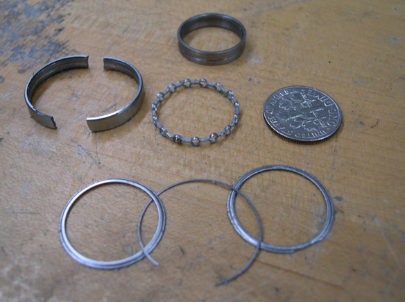
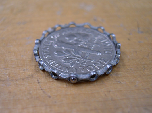
Our embarrassing error did, however, allow us to see just what we were getting for $20. The picture above shows the split-apart races, and the ball cage with one ball left in it. A delicate piece of engineering, that!
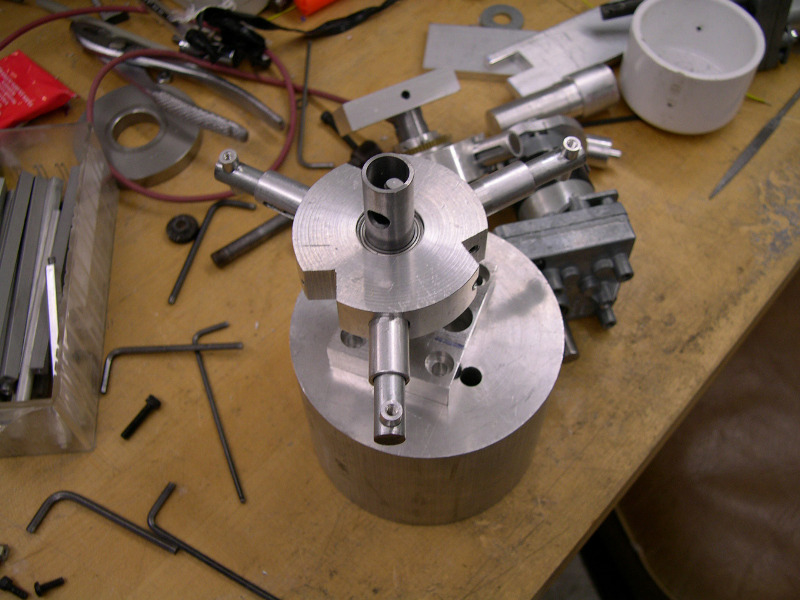
This a completed assembly with motor plate, shaft, hub, three plunger units, and bearings.
Dodgy Electrics
Of course, our electronics could not be neglected while all of this mechanical absurdity was being planned. Much time was spent learning the microcontroller, experimenting with the sensors, and giving thought to power electronics.
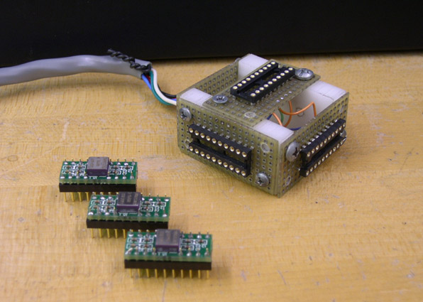
We assembled three of our Analog Devices gyroscopes into this test fixture, which positions them orthogonally and provides power, ground, and signal connections through the large gray cable. This we connected to the HC12 board, which did analog to digital conversion and sent the result out serially to a PC. On this machine I had written a X Window application in Perl/Tk to receive these numbers and display three dials indicating the results obtained from the three gyroscopes. The first 1000 values for each gyro were averaged to discover which voltage corresponded to zero angular velocity (assuming that the device does not move for the first second or so). Then the program integrates the velocities to track position. This was quite accurate—moving the fixture around made the dials swing as expected, and putting it back in its original position brought the dials back to zero. Some slow drift was observed over the course of minutes; probably this could be corrected by using the temperature compensation output of the gyroscope chip.
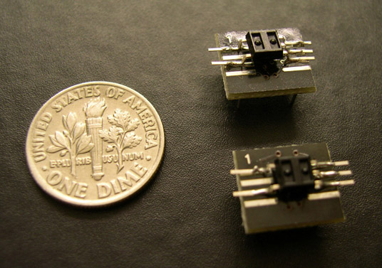
These tiny Hamamatsu (they are actually even smaller than depicted, but they have been soldered onto some interface boards for our convenience) devices were selected to keep track of forward and backward motion in the pipe. They are each pairs of LEDS and photodetectors which are tilted towards each other so as to read the reflection from something passing across the face. In our case, this device could be pointed at a black and white patterned disk mounted to one of our wheels, so that a rising or falling edge is produced in the output signal whenever a black or white zone passes by. This signal is given to the HC12, which includes a convenient counter which keeps updating the number of rising or falling edges in a register.
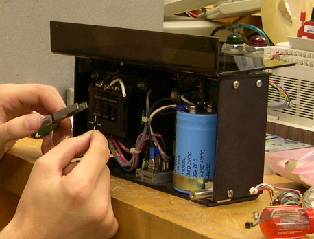
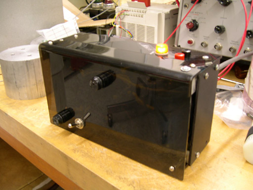
DC power for the entire robot is provided over a tether from a 15 V, 10 A supply, shown above. This open-chassis unit we found in an FAU lab somewhere and equipped with a cover, connectors, switch, fuses, and power light.
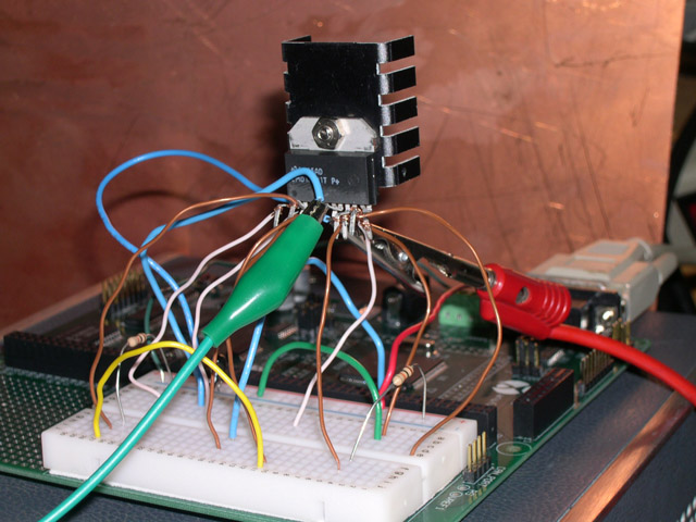
Speed and direction control of our drive motors is facilitated by the H-bridge module seen in this photo. This device came in a type of package like a TO-220 but wider and with many more pins—pins which do not correspond to standard spacing and are themselves wide and flat, necessitating some odd type of socket or crude solder lash-up as seen above. Worse, such treatment makes these pins liable to failure. Where do they crack? Why, at the very root of course, leaving a flush surface of metal 1 mm long and 0.05 mm wide for the frustrated engineer to solder to! When do they crack? In the last hour before you are due to demonstrate your project!
Unfortunately, it seems that many of the full-featured H-bridge modules come in this package (whose name escapes me), due to the need for many pins like a DIP but with the heat-sinking metal plane of the TO-220.
Final Assembly
Pipe Crawler electronics ride in the center module seen above. This metal cage is composed of six long hexagonal standoffs which we found in the boneyard of the Electrical Engineering department. These had threaded ends, one left handed and the other right handed—a curious piece of hardware! We machined off the right hand threads and drilled and tapped that end; then made aluminum endcaps that each accepted three of the threaded ends and three cap-screws for the other three standoffs. The result is a strong, light, hexagonal cage which protects the electronics and serves as the backbone of the robot in that section.
The 18 wheel plungers were particularly tedious to make. These each consisted of:
- A short aluminum tube, slotted for most of its length on the FAU CNC mill
- A steel rod, which slides inside the tube and is drilled in two places
- A small steel pin, inserted into the rod, which engages the tube slot and stops the rod rotating or coming out
- A tubular, threaded standoff, pressed into the rod, which accepts the wheel bolts from each side
- A compression spring that fits into the aluminum tube and forces the rod outward
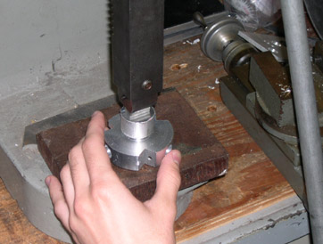
That's a lot of machine shop operations! We set up an assembly line of sorts, with Mark operating the drill press, as seen in the picture below.
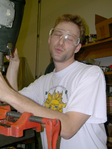
Mark vamps for the camera. One sexy drill-press operator!


The complete pipe-crawler featured no less than 36 wheels!
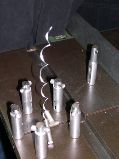

This scene is a piece of machine-shop art named "Nighttime Meeting at the Bandsaw". Nothing permanent was done; it took a lot of fiddling to get the screw "logs" and the smoke stream to stay up on their own. Observe that one plunger has not yet come of age (signified by the wearing of a tubular standoff through the head) and so looks on in envy at the cozy cabal of finished wheel units. One never knows when sleep deprivation, deadline stress, and overwork can result in cheesy art projects!
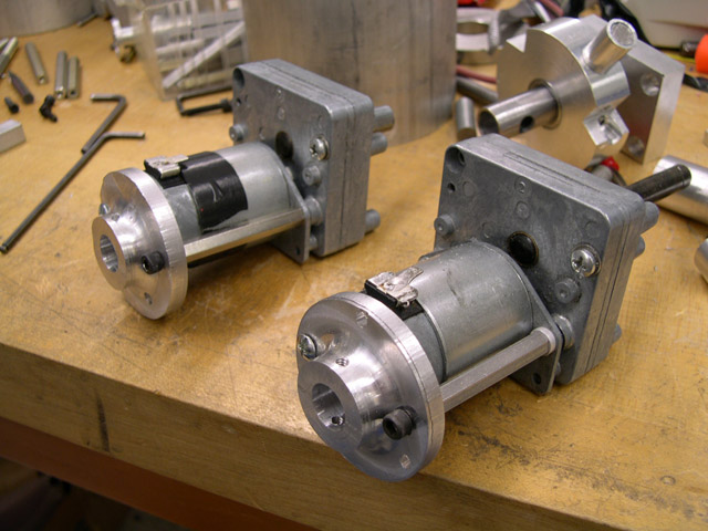
Meanwhile, we were spending a great deal of time on a lot of detail stuff—connecting all of our parts into a finished robot. First, the rear-ends of the motors double as connection points to the rest of the machine, as seen in the picture — the standoff on the side and a aluminum plate underneath (not yet attached in this photo) reinforce the motor body.


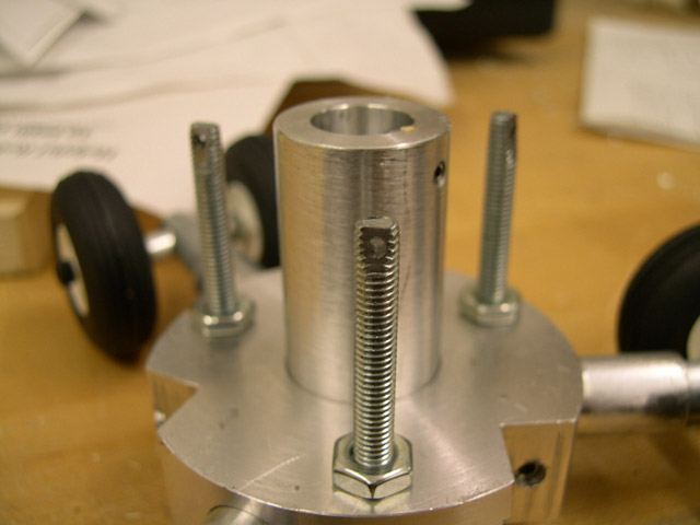
The part on the left above is a brilliant eleventh-hour addition to our project by then-new FAU machinist Jeff Webb (I think he made it for us his first week at FAU—if only he'd been there sooner!). Our previous pinion-units were extremely unreliable, tending to come loose after only a little duty. This one uses tool-pins to stop the gear from rotating, and a large countersunk screw to keep it firmly on the face. On the right, one of these new parts finds its home in a screw drive unit—so THAT'S how it goes together!
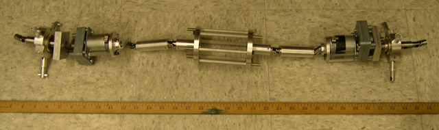
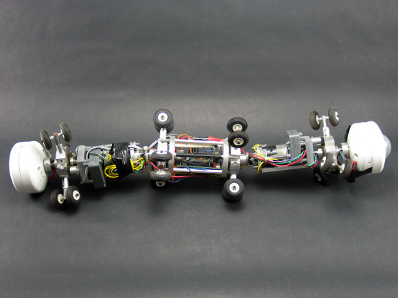
Here we see the machine taking on the desired serpentine shape. We have, from left to right, a drive unit, a static unit intended to support a ring of unpowered wheels, the electronics cage, another static unit, and another screw drive.
We added static guide wheels at both ends; the details of these can be seen in the two photos. The three threaded rods are screws with tiny holes drilled into ground flats at the ends; we intended these to serve as mounting points for joint stiffening springs. This was not the best idea we ever had. The triad of tension springs only worked in that some (those on the inside of the turn) would buckle when compressed too far, and the outside springs would therefore cause a useful moment in the joint, without the need for an active solution. But spring-buckling is not very reliable, particularly as it could cause the loop ends of the spring to unseat themselves.
Rage Against the Machine

We took some time out of our personal engineering drama to amuse ourselves with that of another team: the FAU walking robot (in our defense, this was partly in retialiation for certain individuals using our electronics cage as a rather nice toilet paper roll).
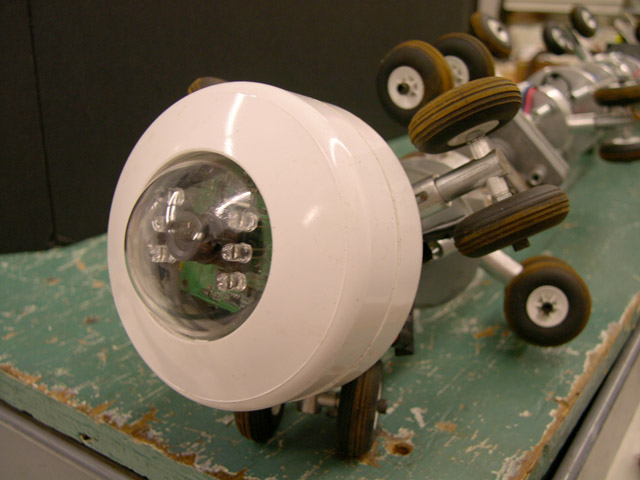
The face of the pipe-crawler: a camera housing made out of two PVC pipe endcaps turned on the lathe (awful smell, that). The lens of our camera is visible behind the clear dome.

The last three days were spent in a daze of last-minute work. Mr. Wasi did not sleep at all during this period; Mark slept only the first night, as did I. We came to the final presentation half-dead. Sheraz fell asleep during the actual presentation. Mark entered some kind of stuttering trance while speaking to the crowd, and needed rescuing. At least the demonstration was well-received, and all seemed very impressed with the intricate mechanism and obvious enormous effort expended on the project.
All three of us later reported falling asleep while driving our cars home afterward Sheraz found himself 'suddenly' in the next lane with a truck honking at him). I could not rouse myself to do anything for a month.
If I HAD to Do it Again
The best suggestions I can give for those working on such a project in the future: make each unit between articulations as small and as short as possible. Try to spread the power around by having many, less powerful drives instead of only two large ones. Of course, this means a lot of very tiny machining—it would be best if some simple way could be found to make a lot of small drives, perhaps powering them with hydraulic or pneumatic pressure.
And, of course, pick a less ambitious project—but don't go too far in this direction, either. After all, as John Stuart Mill observed, “A pupil from whom nothing is ever demanded which he cannot do never does all he can.” Too many of the next generations of FAU students just interfaced a basic stamp with some motors and lights and called it a multi-disciplinary senior project.
In our time, FAU also saw students building a hexapod walking robot, a scratch-built off-road vehicle, and a golf cart that drove itself by GPS. Such projects are rare today, only a few semesters later. I'd rather the students working now reached a little bit farther than they do—even if they don't quite grasp the objectives in the end.